
KostaDiagnosta
-
Постов
824 -
Зарегистрирован
-
Посещение
-
Победитель дней
2
Тип контента
Профили
Форумы
Загрузки
Сообщения, опубликованные KostaDiagnosta
-
-
1 час назад, solinoid сказал:
лаунч нужно брать компания чисто китайская
Вот только в Лаунче официальном Джили запретили как-то добавлять свои марки. Щас не знаю
-
6 часов назад, ivan34 сказал:
вышел новый бюджетный прибор Foxwell
что за модель?
-
6 минут назад, Student сказал:
утилитой скачать установочный пакет 9.85 и установить, потом из папки инсталл всё скопировать в корень диска С. И всё работает, проверил.
Уже разобрался. Тогда из архива нужно убрать уже скачанный, чтобы не смущал
-
11 часов назад, Alex199 сказал:
Выкладываю ссылку, вылеченая, не ругается на отсутсвие связи с сервером https://cloud.mail.ru/public/4vgT/JVwyfXzfx
Чтото не понятно как устанавливать. Тупо через распаковку не работает
-
Ну так ищите, куда делись вторые 5 вольт. Проводка, датчик давления фреона, эбу
- master8607, werne и LEO_NEED
-
 3
3
-
26 минут назад, janis1 сказал:
К моему движку M9R858 схема жгутов от F4R как-то не очень подходит.
-
23 минуты назад, janis1 сказал:
Мне кажется вы ошибаетесь, судя по маркировке сбоку иллюстрации это F4R.
Откройте первую схему и посмотрите верхний левый угол.
А разьемы находятся одинаково у всех
-
1 час назад, janis1 сказал:
А на какой двигатель эта схема жгутов?
У меня движок M9R.
M9R
-
40 минут назад, janis1 сказал:
К сожалению схемы на это авто у меня нет, если можно помогите пожалуйста со схемой по VIN.
Есть такая схема от 2008 года. Думаю не отличается сильно
103 - генератор
419 - климат
247 - приборка
Смотри разьем R262 там часто водичка поработала
-
36 минут назад, werne сказал:
Ищу сток бдм
0281014893
1037394114
Заранее спасибо
Вот такой есть
Пардон, не заметил про BDM!
VW_T5_2.5_TDI_2006_Turbo-Diesel___96.4KWKW_Bosch__070906016EC_394114_81CC.Original
-
54 минуты назад, buch сказал:
HW: 2C1AFC
SW: PUQIAM3.HEX
VIN nr.: WF0VXXBDFV2M46543
SW ver.:
Spare:
Engine:
HW Ver.:
SW upg.:
Installation: EEC-V TDDiТак это вы предлагаете, или что?
-
-
-
-
есть информация ведомого поиска по этим кодам из Chilton
Я бы начал с датчика
Если нужно прикреплю схемы
СпойлерP0AA6-00-HYBRID BATTERY VOLTAGE SYSTEM ISOLATION FAULT
For a complete HIGH VOLTAGE DISTRIBUTION SYSTEM wiring diagram, (refer to the Wiring Information).
Theory of Operation
The Battery Pack Control Module (BPCM) is contained within the High Voltage Battery Pack. The BPCM provides battery management and system functionality in conjunction with Cell Supervision Circuits (CSCs) that monitor and balance the battery cells as well as the monitoring of related external support systems. The CSCs are also located within the High Voltage Battery Pack. The BPCM is the High Voltage Interlock (HVIL) power source and communicates with the vehicle via CAN-C bus. The main functions of the BPCM are high-voltage bus and pre-charge contactor control, battery pack current, voltage and temperature sensing, CAN communication, fault detection and reporting. Diagnosing any DTC related to the BPCM should start with verifying that all fuses, wiring and connections critical to proper system operations are in good repair, securely installed and connected.
When Monitored and Set Conditions
When Monitored:
This diagnostic runs periodically when the following conditions are met:
Ignition on and the contactors are closed.
Set Conditions:
This DTC will set if the Battery Pack Control Module detects that any High Voltage component or cable has developed an isolation failure.
Default Actions:
Malfunction Indicator Lamp (MIL) on.
HEV warning lamp on.
Possible Causes
ANY HIGH VOLTAGE COMPONENT OR CABLE THAT HAS LOST ISOLATION
ANY HIGH VOLTAGE COMPONENT INTERNALLY SHORTED
BATTERY PACK CONTROL MODULE (BPCM)
WARNING
On vehicles equipped with the high voltage system, you must thoroughly read and follow all High Voltage Safety procedures. In addition, before performing any diagnostic or service procedure near a high voltage component, you must perform the High Voltage Power Down. Failure to follow these instructions may result in possible serious or fatal injury.
Always power down the High Voltage System before performing diagnostic tests or repairs to the High Voltage system. (Refer to Electrified Powertrain System/Electric Powertrain Control/Standard Procedure).
Always perform the Pre-Diagnostic Troubleshooting procedure before proceeding. (Refer to Refer to 28 - DTC-Based Diagnostics/MODULE, Battery Pack Control (BPCM)/Standard Procedure).
Diagnostic Test
CHECK FOR AN ACTIVE DTC
Ignition on
NOTE
Diagnose any other BPCM and HCP DTCs before continuing. Especially P0E15-00 and P0E19-00 DTCs.
With the scan tool, record and erase BPCM DTCs.
NOTE
Most BPCM DTCs will require the EVSE to be disconnected in order to clear.
Turn the ignition off. Disconnect scan tool, Close all doors. Wait 3 minutes.
Turn the ignition on. Wait 3 minutes.
With the scan tool, read DTCs.
Is the DTC active?
Yes
Go To >>>
No
Perform the TESTING FOR AN INTERMITTENT CONDITION procedure. (Refer to DTC-Based Diagnostics/Standard Procedure).
DISABLE HIGH VOLTAGE BATTERY CONTACTORS WITH THE SCAN TOOL
Press the ignition ON.
With the scan tool, verify that there are no HVIL DTCs
NOTE
Scan tool HVIL Vehicle and Battery Pack Data should show “Pass.”
With the scan tool, perform “Disable HV Battery Contactors.”
With the scan tool, verify that the HV Battery Contactors are disabled by verifying the contactor status as “Open.”
With the scan tool, verify that there are no Isolation, HVIL, or External Isolation DTCs present.
NOTE
If Isolation DTCs are present, perform “High Voltage Isolation Fault” routine with the scan tool.
With the scan tool, erase all DTCs.
Press the ignition OFF.
Remove scan tool from the DLC.
Close all doors.
Perform CAN Bus sleep cycle. (Wait until cluster display goes blank).
Press the ignition ON.
Wait one minute.
With the scan tool, read DTCs.
Is P1E1B-00 active?
Yes
Replace the High Voltage Battery Pack in accordance with the Service Information. (Refer to Electrified Powertrain System/High Voltage Battery/BATTERY/Removal and Installation).
Perform the BATTERY PACK CONTROL MODULE (BPCM) VERIFICATION TEST. (Refer to DTC-Based Diagnostics/MODULE, Battery Pack Control (BPCM)/Standard Procedure).
No
Enable Contactors with the scan tool and Go To >>>
CHECK THE HV COOLANT HEATER STATUS WITH THE SCAN TOOL
With the scan tool, under HCP Data, check the HV Coolant Heater Status.
Is the HV Coolant Heater Status “Locked Permanently” or “Locked Until Next Service?”
Yes
If status is “Locked Permanently,” replace the HV Coolant Heater in accordance with the Service Information.
If status is “Locked Until Next Service,” perform scan tool routine, “Cabin Overheat Lock Reset” and retest. If status returns “Locked Permanently” replace the HV Coolant Heater in accordance with the Service Information.
Perform the BATTERY PACK CONTROL MODULE (BPCM) VERIFICATION TEST. (Refer to DTC-Based Diagnostics/MODULE, Battery Pack Control (BPCM)/Standard Procedure).
No
Go To >>>
CHECK THE BATTERY COOLANT HEATER (BCH) STATUS WITH THE SCAN TOOL
With the scan tool, under HCP Data, check the Battery Heater Status.
Is the Battery Heater Status “Locked Permanently or “Locked Until Next Service?”
Yes
If status is “Locked Permanently,” replace the Battery Coolant Heater (BCH) in accordance with the Service Information. (Refer to 12 - Electrified Powertrain System/Battery Cooling/HEATERS/Removal and Installation).
If status is “Locked Until Next Service,” perform scan tool routine, “Battery Overheat Lock Reset” and retest. If status returns “Locked Permanently” replace the Battery Coolant Heater (BCH) in accordance with the Service Information. (Refer to 12 - Electrified Powertrain System/Battery Cooling/HEATERS/Removal and Installation).
Perform the BATTERY PACK CONTROL MODULE (BPCM) VERIFICATION TEST. (Refer to DTC-Based Diagnostics/MODULE, Battery Pack Control (BPCM)/Standard Procedure).
No
Perform High Voltage Isolation Test and repair short in High Voltage circuits, repair as necessary. (Refer to Electrified Powertrain System/Electric Powertrain Control/Standard Procedure).
Once the short has been found and repaired. Replace the High Voltage Battery Pack in accordance with the Service Information. (Refer to Electrified Powertrain System/High Voltage Battery/BATTERY/Removal and Installation).
СпойлерP0ABC-00-HYBRID BATTERY PACK VOLTAGE SENSE A CIRCUIT LOW
For a complete HIGH VOLTAGE DISTRIBUTION SYSTEM wiring diagram, (refer to the Wiring Information).
Theory of Operation
The Battery Pack Control Module (BPCM) is contained within the High Voltage Battery Pack. The BPCM provides battery management and system functionality in conjunction with Cell Supervision Circuits (CSCs) that monitor and balance the battery cells as well as the monitoring of related external support systems. The CSCs are also located within the High Voltage Battery Pack. The BPCM is the High Voltage Interlock (HVIL) power source and communicates with the vehicle via CAN-C bus. The main functions of the BPCM are high-voltage bus and pre-charge contactor control, battery pack current, voltage and temperature sensing, CAN communication, fault detection and reporting. Diagnosing any DTC related to the BPCM should start with verifying that all fuses, wiring and connections critical to proper system operations are in good repair, securely installed and connected.
When Monitored and Set Conditions
When Monitored:
This diagnostic runs continuously when the following conditions are met:
Ignition on.
Set Conditions:
This DTC will set if the Battery Pack Control Module detects a fault with internal voltage sense circuits.
Default Actions:
Malfunction Indicator Lamp (MIL) on.
Possible Causes
BATTERY PACK CONTROL MODULE (BPCM)
WARNING
On vehicles equipped with the high voltage system, you must thoroughly read and follow all High Voltage Safety procedures. In addition, before performing any diagnostic or service procedure near a high voltage component, you must perform the High Voltage Power Down. Failure to follow these instructions may result in possible serious or fatal injury.
Always power down the High Voltage System before performing diagnostic tests or repairs to the High Voltage system. (Refer to Electrified Powertrain System/Electric Powertrain Control/Standard Procedure).
Always perform the Pre-Diagnostic Troubleshooting procedure before proceeding. (Refer to Refer to 28 - DTC-Based Diagnostics/MODULE, Battery Pack Control (BPCM)/Standard Procedure).
Diagnostic Test
CHECK FOR SYSTEM VOLTAGE DTCS IN ALL MODULES
WARNING
On vehicles equipped with the high voltage system, you must thoroughly read and follow all High Voltage Safety procedures. In addition, before performing any diagnostic or service procedure near a high voltage component, you must perform the High Voltage Power Down. Failure to follow these instructions may result in possible serious or fatal injury.
Read the HIGH-VOLTAGE SAFETY PROCEDURES, (Refer to Electrified Powertrain System/Electric Powertrain Control/Standard Procedure).
When the HIGH-VOLTAGE POWER-DOWN PROCEDURE is necessary, (Refer to Electrified Powertrain System/Electric Powertrain Control/Standard Procedure).
Repair any Low or High Voltage DTCs in HCP, BPCM, PCM, or IDCM before proceeding and recheck operation. (Refer to DTC-Based Diagnostics/MODULE, Battery Pack Control (BPCM)/Standard Procedure).
With the scan tool, read DTCs in all Electronic Control Units (ECUs) and record on the repair order.
For future reference, with the scan tool, run and save a Vehicle Scan Report and all related recorded data.
Are there any system voltage high or low DTCs present in any modules?
Yes
Diagnose and repair the low voltage system or battery issue. Erase DTCs and retest.
Perform the BATTERY PACK CONTROL MODULE (BPCM) VERIFICATION TEST. (Refer to DTC-Based Diagnostics/MODULE, Battery Pack Control (BPCM)/Standard Procedure).
No
Go To >>>
CHECK THE BPCM POWER AND GROUND CIRCUITS
Load test the Fused B+ and ground circuits at the BPCM.
Did the circuits pass a load test?
Yes
If all powers and grounds are ok, replace the High Voltage Battery Pack in accordance with the Service Information. (Refer to 12 - Electrified Powertrain System/High Voltage Battery/BATTERY/Removal and Installation).
Perform the BATTERY PACK CONTROL MODULE (BPCM) VERIFICATION TEST. (Refer to DTC-Based Diagnostics/MODULE, Battery Pack Control (BPCM)/Standard Procedure).
No
Repair the faulty power or ground circuit. Erase DTCs and retest.
Perform the BATTERY PACK CONTROL MODULE (BPCM) VERIFICATION TEST. (Refer to DTC-Based Diagnostics/MODULE, Battery Pack Control (BPCM)/Standard Procedure).
-
Научитесь грамотно писать марку и другие данные.
-
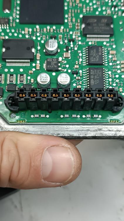
Опытным путем выяснил, что массируется блок через блок клапанов, массу можно подавать на пин 2 на малом разъёме(или на крайние пины черной планки - на фото)
Тем не менее, подключение на столе успехом не увенчалось. Очевидно, напряму к can не возможно.
Блок был инсталлирован на авто, после ремонта пинов разъема, успешно прошел "электронную загрузку передач" и авто на ходу.
Всем спасибо, тему закрываю
-
1 минуту назад, ВИТКОМ сказал:
Доброго. Через зелено-желтый провод. Проверьте в разъеме.
Нет такого. Ни в схеме, ни в разьеме
-
1 минуту назад, 1800677 сказал:
Вопрос интересный, скорее всего так и есть, через блок клапанов.
Да, скорее всего так, сейчас вскрою, проверю
1 минуту назад, 1800677 сказал:А в чем кстати проблема с коробкой?
Нет массы на датчики, есть подозрение на ЭБУ, нужно подключить на столе, машина на другом СТО
-
Только что, 1800677 сказал:
Ну он прикручен к КПП
Это понятно, как в ЭБУ масса попадает? Если только через контакты блока клапанов, ведь корпус -пластиковый
-
6 минут назад, 1800677 сказал:
Нашел еще кое что полезное. Думаю с этим можно решить возникшие проблемы. Но схема все же для DV6, но там по сути в части подключения разницы не будет, кроме CAN двигателя.
MAKP (1).pdf 248.61 kB · 0 загрузок Компьютер автоматизированной коробки передач.pdf 96.49 kB · 0 загрузок Роботизированная коробка передач типа MCP.pdf 170.74 kB · 0 загрузок
Смотрю все схемы и чтото не могу понять, как реализована масса на этом ЭБУ
-
2 минуты назад, 1800677 сказал:
В VIN не хватает одного символа.
vf7uarhjh45165714
-
4 минуты назад, 1800677 сказал:
Magnetti Marelli CFC300
Именно такой
-
В 09.02.2024 в 21:22, Du4 сказал:
К сожалению, схема не подходит


VNCI 6154A - обзор/отзывы/софт
в VCDS (он же Vag-Com)
Опубликовано
Он имел ввиду, что до 2005 года В ТОМ ЧИСЛЕ