Лидеры

Популярный контент
Показан контент с высокой репутацией 24.07.2022 во всех областях
-

Carmin v4.0.8 Full
solid и 3 других отреагировал gladiator007 за тема
Carmin v4.0.8 Carmin.txt4 балла -
ID: 184BE8BB6080515A9F6EFB02B729EF01 Ver: 17.10.XXX NA: 94ddd0523518906ab3bef140e9fc9d0750292207230654 EU: 96617256df033bd423f4b4ce38d4919850292207230654 JP: d950cbfb183d0600752223293faa65455ddbd2780bc99c OT: c70da1e495390aad848ce12c01f4f7fc502922072306542 балла
-
 Выложу и здесь... Простая удобная прога для распаковывание сток марок с созданием гаглика и лицензии. Потом можно переименовать папку и запаковать для раздачи. Этим самым вы не спалите свой источник. Можно запустить в смд или бросить зип на прогу usage: launchunpack.exe CHANGFENG_V20_54_CN_989820000000.ZIP or Drag and Drop zip file launchunpack.7z2 балла
 -
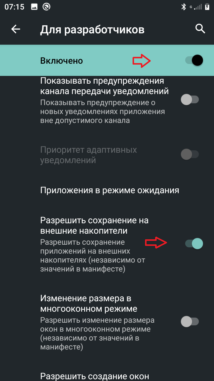
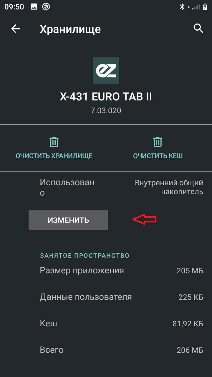
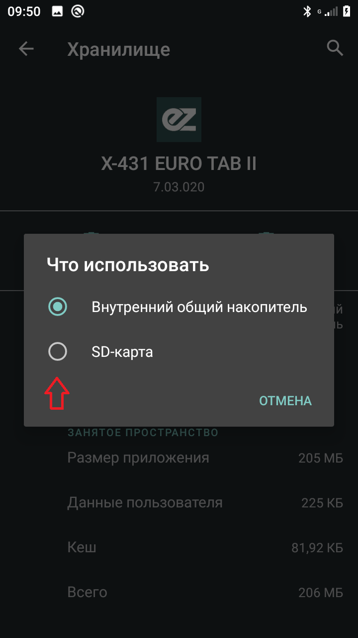
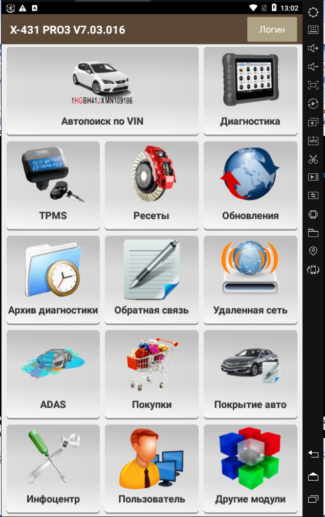
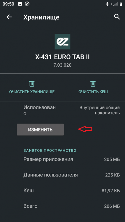
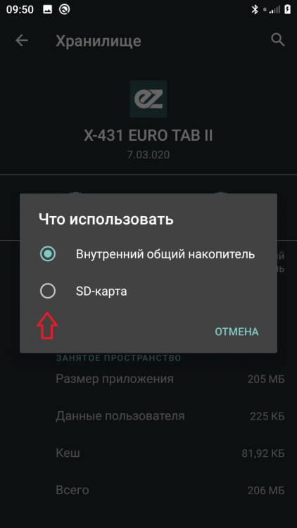
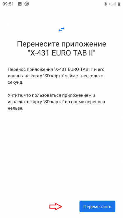
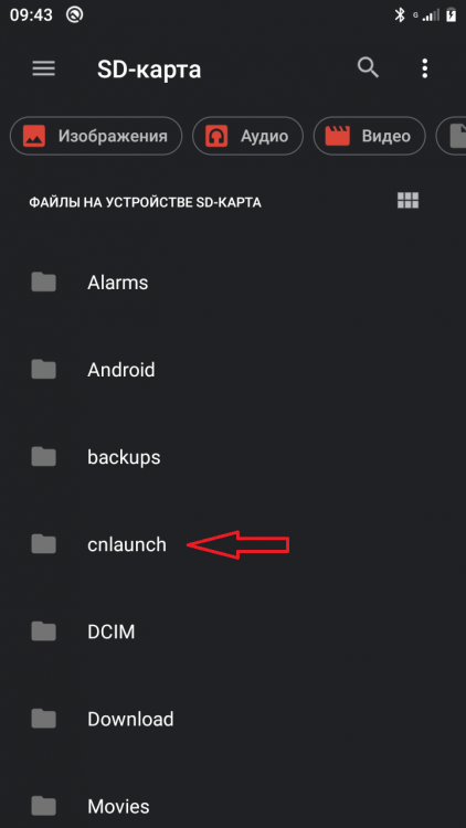
 Перенос приложения на SD-карту в Андроид 10-11. Форматируем SD-карту как внутрений накопитель и после предложения перенести файлы, переносим. Далее в Настройках заходим в пункт О телефоне, в нем находим пункт Номер сборки, тапаем несколько раз до Вы стали разработчиком. Далее Настройки -Система -Дополнительно -Для разработчиков. Заходим в меню Для разработчиков включаем отладку по USB, если нужно Включить журнал HCI Bluetooth. Почти в самом низу Приложения - найти Разрешенить сохранение на внешние накопители и сдвинуть ползунок вправо. Далее устанавливаем любую оболочку, запускаем, закрываем. Идем в Настройки -Хранилище -Внутрений общий накопитель - Другие приложения - находим установленную оболочку и открываем, должен появится пункт изменить. Открываем выбираем SD-карта и перемещаем приложение на SD. Радуемся что появился пункт перенести на SD ))))))))! Перенос приложений на SD_XIAOMI инструкция. - Инструкция в самом низу после картинок Перенос приложений на SD_XIAOMI.rar
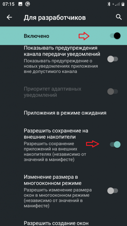
 2 балла
 -
 BimmerLink 2.25.0 + BimmerCode 4.6.0 + Bimmer BTool Expert 3.3.17-expert для BMW (Android apk) BimmerCode позволяет кодировать блоки управления в BMW или Mini, чтобы разблокировать скрытые функции и настроить автомобиль по своему вкусу. Активируйте цифровой дисплей скорости на комбинации приборов или разрешите пассажирам смотреть видео во время движения в системе iDrive. Вы хотите отключить функцию Auto Start / Stop или Active Sound Design? Вы сможете самостоятельно кодировать это и многое другое с помощью приложения BimmerCode. Поддержка авто: 1 Series 2008+ 2 Series, M2 2013+ 2 Series Active Tourer 2014+ 2 Series Gran Tourer 2015+ 3 Series, M3 2008+ 4 Series, M4 2013+ 5 Series, M5 2008+ 6 Series, M6 2008+ 7 Series 2008+ 8 Series 2018+ X1 2009+ X2 2018+ X3, X3 M 2010+ X4, X4 M 2014+ X5, X5 M 2008+ X6, X6 M 2008+ X7 2019+ Z4 2009+ i3 2013+ i8 2013+ Mini 2008+ Toyota Supra 2019+ BimmerLink + BimmerCode + Bimmer BTool Expert.txt1 балл
 -
 Добрый день. Может еще и ключ от квартиры?1 балл
 -
Carly v48.32 Full
serg76 отреагировал gladiator007 за тема
Carly v48.32 Carly1 балл -
 всем привет! С отломом в ЛС помог insaid897 , за что ему огромное спасибо! Правда кармы на + ему в карму у меня не хватает. Кому не жалко - плюсаните и мне, чтобы я мог благодарить тоже плюсом хороших людей. Может кто еще подкинет ссылку на самые свежие правленные марки под новый отлом от 05.2020, которые есть в свободном доступе ?1 балл
 -
есть такой _Lada XRAY (MC9S12XHY256).7z1 балл
-
Скиньте что считали! и в чем проблема ? какой еепром 93с66 или 24с16 ?1 балл
-

Chevrolet Equinox 2019 1.5 турбо-бензин - глюк датчика наддува
SergeiMM отреагировал anisimov83 за тема
DTC P00C7 Diagnostic Instructions Perform the Diagnostic System Check prior to using this diagnostic procedure: Diagnostic System Check - Vehicle Review the description of Strategy Based Diagnosis: Strategy Based Diagnosis An overview of each diagnostic category can be found here: Diagnostic Procedure Instructions DTC Descriptor DTC P00C7 Intake Air Pressure Measurement System - Multiple Sensors Not Plausible Circuit/System Description This system consists of the following components: Barometric Pressure Sensor B65 Intake Manifold Pressure and Air Temperature Sensor This DTC sets when the control module detects an inconsistency between the pressure sensors and cannot identify which sensor failed. Conditions For Running The DTC DTC P0106, P0107, P0108, P2122, P2123, P2127, P2128, P2138, P2610 = Not set Engine=Not Running Time between current ignition cycle and the last time the engine was running=Greater than 10 s Manifold Absolute Pressure=50 to 115 kPa (7.3 to 16.7 PSI) Barometric Pressure=50 to 115 kPa (7.3 to 16.7 PSI) Turbocharger Boost Sensor=50 to 115 kPa (7.3 to 16.7 PSI) Frequency the DTC runs=Continuously - After the running conditions are met Conditions For Setting The DTC Manifold Absolute Pressure & Barometric Pressure= Not within 10 kPa (1.5 PSI) of each other. Actions Taken When The DTC Sets DTCs listed in the DTC Descriptor Category=Type B DTC Conditions For Clearing The DTC DTCs listed in the DTC Descriptor Category=Type B DTC Reference Information Schematic Reference Engine Controls Schematics Connector End View Reference Component Connector End Views - Index Master Electrical Component List Electrical Information Reference Circuit Testing Connector Repairs Testing for Intermittent Conditions and Poor Connections Wiring Repairs DTC Type Reference Powertrain Diagnostic Trouble Code (DTC) Type Definitions Scan Tool Reference Control Module References Circuit/System Verification Ignition - On / Vehicle - In Service Mode Verify DTC P0106, P0107, P0108, P2122, P2123, P2127, P2128, P2138, P2610 is not set. If any of the DTCs are set Refer to: Diagnostic Trouble Code (DTC) List - Vehicle Go to next step: If none of the DTCs are set Verify the scan tool parameter: BARO Sensor= Altitude Versus Barometric Pressure - The value should be within the range listed in the table. MAP Sensor= Altitude Versus Barometric Pressure - The value should be within the range listed in the table. Turbocharger Boost Sensor= Altitude Versus Barometric Pressure - The value should be within the range listed in the table. If not in the specified range {BARO Sensor}Refer to: DTC P2227-P2230 {MAP Sensor}Refer to: {Turbocharger Boost Sensor}Refer to:DTC P0236, P0237, or P0238 Go to next step: If in the specified range All OK. Repair Instructions Perform the Diagnostic Repair Verification after completing the repair: Diagnostic Repair Verification For control module replacement, programming, and setup refer to: Control Module References DTC P0236, P0237, Or P0238 Diagnostic Instructions Perform the Diagnostic System Check prior to using this diagnostic procedure: Diagnostic System Check - Vehicle Review the description of Strategy Based Diagnosis: Strategy Based Diagnosis An overview of each diagnostic category can be found here: Diagnostic Procedure Instructions DTC Descriptor DTC P0236 Turbocharger Boost Sensor Performance DTC P0237 Turbocharger Boost Sensor Circuit Low Voltage DTC P0238 Turbocharger Boost Sensor Circuit High Voltage Diagnostic Fault Information CircuitShort to GroundOpen/High ResistanceShort to VoltageSignal Performance 5 V ReferenceP0236, P0237, P0340, P0365, P0452, P0532, P0641, P2227P0236, P0237, P2227P0236, P0238, P0453, P0641, P2227P0236 SignalP0236, P0237, P2227P0236, P0237, P2227P0236, P0238, P2227P0236 Low Reference-P0098, P0236, P0238, P2227-- Typical Scan Tool Data Boost Pressure Sensor CircuitShort to GroundOpenShort to Voltage Operating Conditions: Engine=Running - Normal Operating Range Parameter Normal Range: Barometric Pressure 240 kPa (34.8 PSI) Maximum 5 V Reference0 kPa (0.0 PSI)0 kPa (0.0 PSI)269 kPa (39 PSI) Signal0 kPa (0.0 PSI)0 kPa (0.0 PSI)269 kPa (39 PSI) Low Reference-269 kPa (39 PSI)- Circuit/System Description For an overview of the component/system, refer to: Compressor Air Intake Turbocharger System Description CircuitDescription 5 V ReferenceRegulated voltage supplied by the control module. SignalThe control module input circuit has an internal resistance connected to 5 V. Low ReferenceGrounded through the control module. ComponentDescription K20 Engine Control ModuleThe control module contains a microprocessor used to process input data to control outputs. The control module controls a series of actuators to ensure optimal engine performance. The control module does this by reading values from a variety of sensors, interprets the data and adjusts the engine actuators accordingly. B111 Turbocharger Boost SensorThe sensor measures the pressures between the turbocharger and the throttle body. When the engine is off or idling, the boost pressure should be the same as the barometric pressure. Under wide-open throttle conditions the pressure will increase considerably. Conditions For Running The DTC P0236 DTC P0106, P0107, P0108, P0237, P0238, P2227, P2228, P2229, P2230 = Not set DTC P0106, P0107, P0108, P0237, P0238=Not pending Ignition On - Engine Off Time between current ignition cycle and the last time the engine was running Greater than 10 s Frequency the DTC runs=Continuously - After the running conditions are met Frequency the DTC runs=Continuously - After the running conditions are met OR DTC P0102, P0103, P0107, P0108, P0111, P0112, P0113, P0114, P0116, P0117, P0118, P0128, P0237, P0238, P0335, P0336, P2227, P2228, P2229, P2230 = Not set DTC P0112, P0113, P0117, P0118 Not pending Engine Speed.400 to 6100 RPM Engine Coolant Temperature=-7 to 125°C (19 to 257°F) Intake Air Temperature (IAT) Sensor CircuitIf between -20 and 125°C (-4 and 257°F) Frequency the DTC runs=Continuously - After the running conditions are met P0237 & P0238 Ignition=On or Engine Running Frequency the DTC runs=Continuously - After the running conditions are met Conditions For Setting The DTC P0236 Boost Pressure SensorOut Of Range OR Boost Pressure Sensor=Less than 50 kPa (7.3 PSI)orGreater than 115 kPa (16.7 PSI) Ignition On - Engine Off OR MAP Sensor.-Barometric Pressure SensorLess than 10 kPa (1.6 PSI) & Turbocharger Boost Sensor-MAP Sensor.Greater than 10 kPa (1.6 PSI) & Turbocharger Boost Sensor-Barometric Pressure Sensor Greater than 10 kPa (1.6 PSI)Ignition On - Engine Off P0237 Boost Pressure Sensor=Less than 0.66 V - For greater than 5 s P0238 Boost Pressure Sensor=Greater than 4.3 V - For greater than 5 s Actions Taken When The DTC Sets DTCs listed in the DTC Descriptor Category=Type A DTC The ECM will disable the boost-pressure control.= Reduced Engine Power Conditions For Clearing The DTC DTCs listed in the DTC Descriptor Category=Type A DTC Reference Information Schematic Reference Engine Controls Schematics Connector End View Reference Component Connector End Views - Index Master Electrical Component List Electrical Information Reference Circuit Testing Connector Repairs Testing for Intermittent Conditions and Poor Connections Wiring Repairs DTC Type Reference Powertrain Diagnostic Trouble Code (DTC) Type Definitions Scan Tool Reference Control Module References Circuit/System Verification Ignition - On / Vehicle - In Service Mode Verify DTC P0641, P0651, P0697, P06A3, P06D2 is not set.If any of the DTCs are set Refer to: Diagnostic Trouble Code (DTC) List - Vehicle Go to next step: If none of the DTCs are set If you were sent here from DTC P0068, P0101, P0106, P0121, P01101 - Refer to: Circuit/System Testing. Verify the scan tool parameter: Throttle Body Idle Air Flow Compensation Less than 90%If greater than 90% Refer to: Throttle Body Inspection and Cleaning Go to next step: If less than 90% Perform the scan tool control function: Throttle Sweep - Start Verify the scan tool parameter: Throttle Position Sensors 1 and 2=Agree If not the specified state Refer to:DTC P0121-P0123, P0222, P0223, P16A0-P16A2, or P2135 Go to next step: If the specified state Verify the scan tool parameter: BARO Sensor=The value should be within the range listed in the table: Altitude Versus Barometric PressureIf not in the specified range Refer to: DTC P2227-P2230 Go to next step: If in the specified range Verify the following parameter is within 3 kPa (.4 PSI) of the actual barometric pressure: MAP SensorIf not in the specified range Refer to:DTC P0106, P0107, or P0108 Go to next step: If in the specified range Engine idling. Verify the scan tool parameter: MAP Sensor=26 to 52 kPa (3.8 to 7.5 PSI) - The value should change with accelerator pedal input.If not in the specified range or does not change Refer to:DTC P0106, P0107, or P0108 Go to next step: If in the specified range and changes Observe the scan tool parameter: MAF Sensor & Engine Speed. Increase the engine speed slowly to 3, 000 RPM and then back to idle. Verify the scan tool parameter: MAF Sensor=The value should change smoothly and gradually as the engine speed is increased and decreased.If the value does not change smoothly and gradually Refer to:DTC P0101 Go to next step: If the value changes smoothly and gradually Verify the following parameter is within 3 kPa (.4 PSI) of the actual barometric pressure: Boost Pressure SensorIf not in the specified range Refer to: Circuit/System Testing Go to next step: If in the specified range Verify the following parameters are within 20 kPa (2.9 PSI) of each other: - 1-2 Shift Time @ Wide Open Throttle MAP Sensor Boost Pressure Sensor If not within 20 kPa (2.9 PSI) of each other Refer to: Circuit/System Testing Go to next step: If within 20 kPa (2.9 PSI) of each other Operate the vehicle within the Conditions for Running the DTC. You may also operate the vehicle within the conditions that you observed from the Freeze Frame/Failure Records data. Verify the DTC does not set. If the DTC sets Refer to: Circuit/System Testing Go to next step: If the DTC is not set All OK. Circuit/System Testing Verify no other DTCs are set.If any of the DTCs are set Refer to: Diagnostic Trouble Code (DTC) List - Vehicle Go to next step: If none of the DTCs are set Verify the conditions listed in the table do not exist: Loose clamps, cracks, or other damages to the intake system. Collapsed or restricted intake air duct. Clogged air cleaner. Vacuum hoses with kinks, leaks, or improper connections. Missing, restricted or leaking exhaust components.-Refer to: Symptoms - Engine Exhaust Leaks at the intake manifold or throttle body. If a condition exists Repair as necessary Go to next step: If no conditions exist Ignition/Vehicle & All vehicle systems - OffNOTE: It may take up to 2 min for all vehicle systems to power down before an accurate ground or low reference circuit continuity test can be performed. Disconnect the electrical connector: B111 Turbocharger Boost SensorIt may take up to 2 min for all vehicle systems to power down before an accurate ground or low reference circuit continuity test can be performed. Test for less than 5 ohms between the test points: Low Reference circuit terminal 2 & Ground If 5 ohms or greater Disconnect the electrical connector :X3 @ K20 Engine Control Module Test for less than 2 ohms between the test points: Low Reference circuit terminal 2 @ Component harness & The other end of the circuit If 2 ohms or greater - Repair the open/high resistance in the circuit. If less than 2 ohms - Replace the component: K20 Engine Control Module Go to next step: If less than 5 ohms Ignition - On / Vehicle - In Service Mode Test for 4.8 to 5.2 V between the test points: 5 V Reference circuit terminal 1 & Ground If less than 4.8 V Ignition/Vehicle - Off Disconnect the electrical connector: X3 @ K20 Engine Control Module Test for infinite resistance between the test points: 5 V Reference circuit terminal 1 @ Component harness & Ground If less than infinite resistance - Repair the short to ground on the circuit. Go to next step: If infinite resistance Test for less than 2 ohms between the test points: 5 V Reference circuit terminal 1 @ Component harness & The other end of the circuit If 2 ohms or greater - Repair the open/high resistance in the circuit. If less than 2 ohms - Replace the component: K20 Engine Control Module If greater than 5.2 V Ignition/Vehicle - Off Disconnect the electrical connector: K20 Engine Control Module Ignition - On / Vehicle - In Service Mode Test for less than 1 V between the test points: 5 V Reference circuit terminal 1 @ Component harness & Ground If 1 V or greater - Repair the short to voltage on the circuit. If less than 1 V - Replace the component: K20 Engine Control Module Go to next step: If between 4.8 and 5.2 V Verify the scan tool parameter: Boost Pressure Sensor=Greater than 4.5 V If 4.5 V or less Ignition/Vehicle - Off Disconnect the electrical connector: K20 Engine Control Module Test for infinite resistance between the test points: Signal circuit terminal 3 @ Component harness & Ground If less than infinite resistance - Repair the short to ground on the circuit. If infinite resistance - Replace the component: K20 Engine Control Module Go to next step: If greater than 4.5 V Connect a 3 A fused jumper wire between the test points: Signal circuit terminal 3 & Low Reference circuit terminal 2 Verify the scan tool parameter: Boost Pressure Sensor = Less than 0.2 V If 0.2 V or greater Ignition/Vehicle - Off & Remove - Jumper wire(s) Disconnect the electrical connector: K20 Engine Control Module Ignition - On / Vehicle - In Service Mode Test for less than 1 V between the test points: Signal circuit terminal 3 @ Component harness & Ground If 1 V or greater - Repair the short to voltage on the circuit. Go to next step: If less than 1 V Ignition/Vehicle - Off Test for less than 2 ohms between the test points: Signal circuit terminal 3 @ Component harness & The other end of the circuit If 2 ohms or greater - Repair the open/high resistance in the circuit. If less than 2 ohms - Replace the component: K20 Engine Control Module Go to next step: If less than 0.2 V Test or replace the component: B111 Turbocharger Boost Sensor Component Testing Dynamic Test - Using Vehicle Harness Ignition/Vehicle - OffNOTE: Circuit/System Testing must be performed before proceeding with Component Testing. Remove the component: B111 Turbocharger Boost Sensor - Leave the electrical connector connected. Install the special tool: EN-23738-A Vacuum Pump @B111 Turbocharger Boost Sensor Use the tool to achieve a gauge reading between -13 and -21 kPa (-0.13 and -0.21 bar, -3.8 and -6.2 in Hg). Verify the scan tool parameter: Boost Pressure Sensor=Decreases between 13 and 21 kPa (1.9 and 3.0 PSI) If the parameter does not decrease between 13 and 21 kPa (1.9 and 3.0 PSI) Replace the component: B111 Turbocharger Boost Sensor Go to next step: If the parameter decreases between 13 and 21 kPa (1.9 and 3.0 PSI) Use the tool to achieve a gauge reading between -30 and -38 kPa (-0.3 and -0.38 bar, -8.8 and -11.2 in Hg). Verify the scan tool parameter: Boost Pressure Sensor=Decreases between 30 and 38 kPa (4.4 and 5.5 PSI) If the parameter does not decrease between 30 and 38 kPa (4.4 and 5.5 PSI) Replace the component: B111 Turbocharger Boost Sensor Go to next step: If the parameter decreases between 30 and 38 kPa (4.4 and 5.5 PSI) All OK. Dynamic Test - Using Jumper Wires Ignition/Vehicle - Off Remove the component: B111 Turbocharger Boost Sensor Connect a 3 A fused jumper wire between the test points: 5 V Reference terminal 1 & 5 V Connect a jumper wire between the test points: Low Reference terminal 2 & Ground Connect a DMM between the test points: Signal circuit terminal 3 @ B111 Turbocharger Boost Sensor & Ground Install the special tool: EN-23738-A Vacuum Pump @B111 Turbocharger Boost Sensor Use the tool to achieve a gauge reading between 0 and -15 kPa (0 and -0.15 bar, 0 and -4.4 in Hg). Verify the DMM displays between 0.2 and 4.9 V. - The value should not spike or drop out. If not between 0.2 and 4.9 V or has spikes or drops out Replace the component: B111 Turbocharger Boost Sensor Go to next step: If between 0.2 and 4.9 V and there are no spikes or drops out All OK. Repair Instructions Perform the Diagnostic Repair Verification after completing the repair: Diagnostic Repair Verification Turbocharger Air Pressure Sensor Replacement - B111 Turbocharger Boost Sensor For control module replacement, programming, and setup refer to: Control Module References1 балл -

Infinity FX50 5л. 2009 не проходит адаптация
dima.aleksandrov отреагировал SErgey_k за тема
Это совсем кардинально, тереть весь еепром. Проще родной почистить.1 балл -

Infinity FX50 5л. 2009 не проходит адаптация
dima.aleksandrov отреагировал dyrokol за тема
Вбиваете в еепром "FFFFFF.......FFFF" это и есть как бы чистый еепром, но при этом вам нужно будет прописать ключи, а возможно возникнут и другие проблемы На сколько знаю но адаптация должна делаться при рабочей температуре ДВС и обороты ДВС должны быть не более 1200, вот из за последнего как раз таки и отключают одну форсунку или ограничивают расход воздуха и соответственно процедура проходит в два этапа..........1 балл -
Renault Grand Modus 2008 года ключи прописал. VW Passat B5 ME7.5 в спец функциях ECU Flasher EEProm читает хорошо, но перед записью EEProm нужно нажать кнопку ImmoOff, что бы мусор не записало и тогда пишет правильно1 балл
-

Infinity FX50 5л. 2009 не проходит адаптация
dima.aleksandrov отреагировал oleg213 за тема
хотелось бы посмотреть на FX50 с механикой, да и в целом на s51й с мешалкой😁 самый верный вариант это EEPROM1 балл -
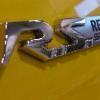
У вас 837ый мотор, т.е. система сименс. 834ый мотор, это делфи. На скрине эталон, лично снятый, многократно заверенный. Все у вас ок с положением валов. А вот статус синхры, который ЭБУ засылает в дату чаще заводит в тупик, чем помогает. Вы с проводами под днищем и с записью стока че нить решили? и обработать вероятность глушения по CAN сигнализацией тоже бы надо. Следы установки есть?
 1 балл
 -
ODBLink, BMW ENET, да и elm-ка китайская должна работать.1 балл
-
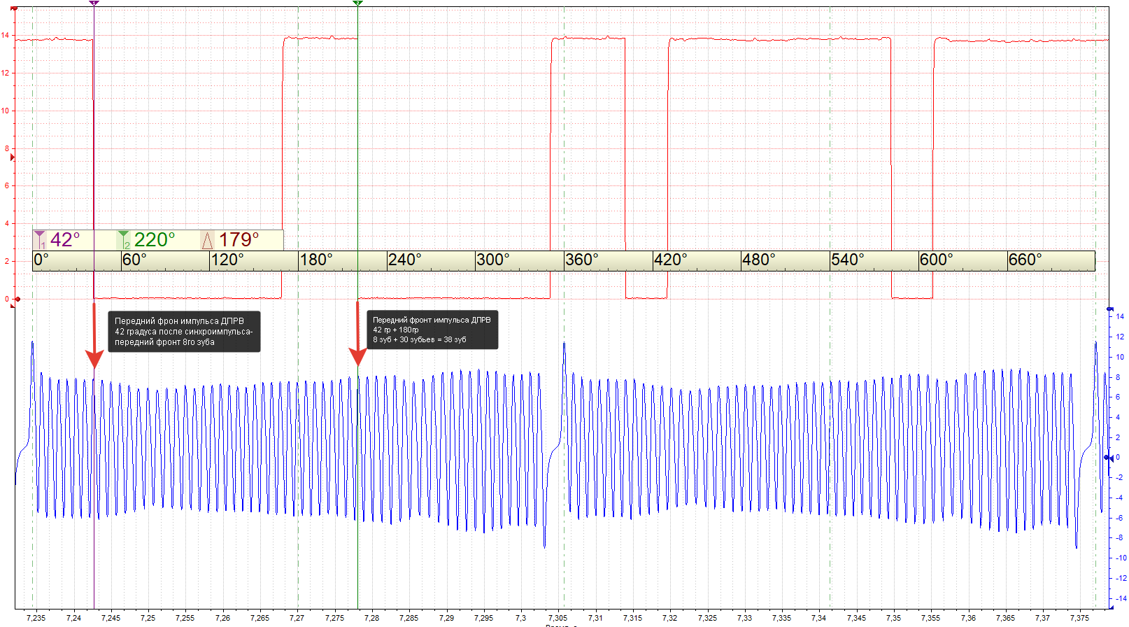
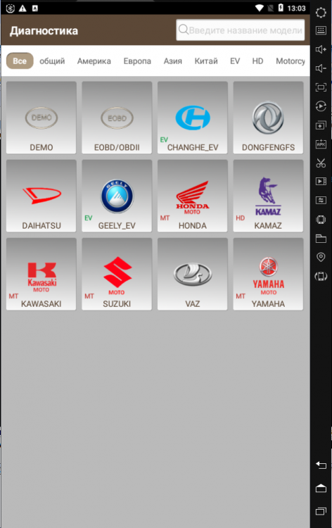
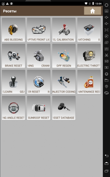
Для тех, кому не нравится ближе к стоку. )))))))))))! X431PRO3S_APP_V7_03_016_RU (для смартфонов) X431PRO3S_APP_V7_03_016_RU.txt
 1 балл
 -
Honda HRV 2019 77960-T7A-A230-M2 R7F701A223 crash+clear renelight мой pinout 77960-T7A-A230-M2 - crash - clear.rar1 балл
-
Откликнувшиеся люди, видать, только умеют тыкать дампы во всякие кальки, типа ипрога Ну а подсказывать вам наверное смысла нет ни какого, раз вы не удосужились выложить содержимое вашего блока0 баллов
-
D0AC-AEA5-8BB7-FBE3-562E-B7FD-7049-6828-D16A-48CF-A3F7-5A53-520E-39BA-8A5D-322E T8213909910 баллов
-
Все равно это не показатель, что надо пилить. Если аккуратно подойти к вопросу, и главное не торопиться, то заднюю (белую) крышку можно снять целой, не повредив обе боковые крышки. Ну а дальше, кто на что горазд, хоть лезвие, хоть детали рвать Красота спасет мир.0 баллов
-
Нужно искать по маске, так как "маска" это предзагруженное программное обеспечение на заводе для определённых авто.0 баллов
-
...что мешает поставить диод паралельно электромуфте?0 баллов